Nimble Radio Remote Updated Installation Instructions
2023 Sistematica Nimble Remote Installation Instructions
Current – 5 Amp per output to a maximum of 7 Amp total suppliable current
INSTALLATION
To ensure correct operation installation must be performed by a qualified installer.
- Position the receiver vertically (with the cable outlet facing downwards)
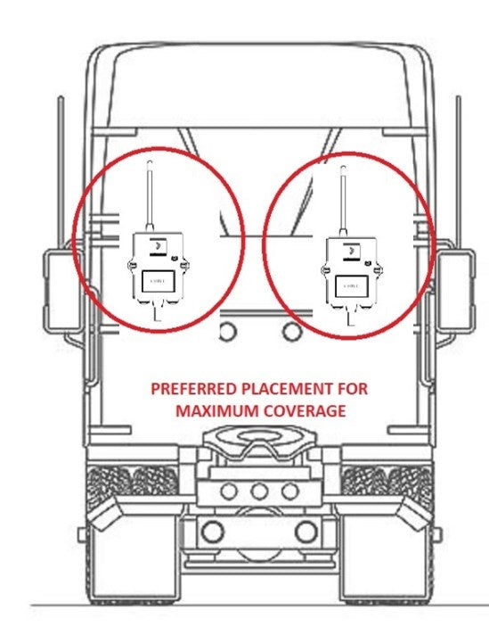
- In order not to compromise reception, the CONTROLLER must not be shielded by steel enclosures, mount the receiver up and out from as much steel plate interference as is possible OR use the optional aerial.
- It is highly recommended to mount at rear of cabin up high as possible and to the operational side or if using both sides to the middle, this will increase range considering trailer interference.

WIRING HARNESS – ONLY REQUIRED TO JOIN POWER + EARTH
|
Colour |
Ref |
Type |
Notes |
|
Green |
1 |
Output Momentary |
Output1 / Tip |
|
Yellow |
2 |
Output Momentary |
Output2 / Lower |
|
Grey |
3 |
Output Momentary |
Output3 (4 button only) |
|
Pink |
4 |
Output Momentary |
Output4 (4 button only) |
|
Red |
5 |
POWER IN |
Power (Aux on only) |
|
Black |
6 |
EARTH |
Earth |
|
White |
7 |
Not used |
Not used |

ELECTRICAL INSTALLATION
- The kit is supplied with a 2 Pin Deutsch plug with F crimp pins (see pic next page)
- It is recommended to connect to Aux Power on signal with a 10 amp fuse.
- DO NOT connect power wire to any other load circuit.
- Connect earth to a suitable and clean earth.
AIR INSTALLATION
S1 – Supply
- Air may come from the existing system air supply using the T fitting supplied.
T1 – Existing TIP air signal
- Remove existing TIP air line from hydraulic valve and redirect to port T1.
- Kit has fittings for both ¼”G and 6mm air line.
T2 – NEW TIP air signal
- Run a new airline from T2 back to the hydraulic valve TIP air port.
- Kit has fittings for both ¼”G and 6mm air line.
L1 – Existing LOWERING air signal
- Remove existing LOWER air line from hydraulic valve and redirect to port T1.
- Kit has fittings for both ¼”G and 6mm air line.
L2 – NEW LOWERING air signal
- Run a new airline from T2 back to the hydraulic valve LOWER air port.
- Kit has fittings for both ¼”G and 6mm air line.
***Air Regulator No Longer Required***

